Computer Graphics (GRK)
Lecture VI
Modelling of 3D objects and scenes
Talking about 3D graphics we usually distinguish two stages. The first stage is modelling of spatial objects and creating the scene containing previously prepared objects and light sources. In the second stage series of operations leading to displaying the scene on the screen is performed. This stage is generally named scene rendering. In this lecture we will deal with model and scene modelling methods.
Modelling of objects
Among different methods of three dimensional objects modelling we may distinguish two groups: methods based on description of the surface of the solid (Brep methods) and volumetric methods.
In Brep group of methods we use both methods describing accurately the surface of modelled solid (so called surface methods) and the methods approximating the surface of the solid. The most important are the methods approximating the outer surface of the solid by polygonal mesh, most frequently by the triangles.
Among volumetric methods the first of all are voxel methods.
Polygonal meshes
In majority of application we use polygonal meshes to describe outer surface. Lateral surface of a solid is described by the set of polygons. In the case of such solids as polyhedrons such representation is quite natural. In the case of surfaces which are not flat we use polygonal approximation of the surface
Examples of approximation of lateral surface of a few objects by polygons are shown in Fig. VI.1. Among the others two representations of sphere surface are shown - please wonder about the method of finding such representations and differences between these representations.
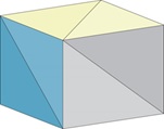
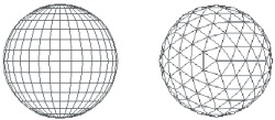
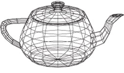
Fig. VI.1. Examples of polygonal approximation of objects surface
Let us pay attention to the way of description of such meshes. As a rule we use two tables. One serves for storing information about mesh nodes/vertices, the another store the information about specific polygons. The example of such description is shown in Fig. VI.2.

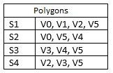
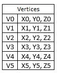
Fig. VI.2. The method of polygonal mesh description
The advantage of such method is saving memory locations (each vertex is written only once) and during possible geometric transformation the calculations concerning considered vertex are also executed only once (please wonder what would happen if each vertex was described independently).
In practice we frequently use triangle meshes. It results from the fact, that each triangle define in a unique way the surface on which it lies. The number of approximating polygons (triangles) may be very big. Nothing exceptional are the cases of surface approximation by a few hundreds of thousands of triangles. The more details contains the lateral surface, the more triangles are needed for approximation. We should remember the need of compromise between accuracy of surface modelling and rendering time - the greater the number of polygons the longer is the rendering time.
Correct triangle mesh should be continuous (without holes). The mesh should have such feature, that each edge of the mesh should belong only to two triangles (possibly to one triangle if its boundary triangle of a mesh) and each mesh vertex has single continuous set of triangles around. Moreover the mesh should be oriented. It means that all normal vectors to specific triangles should be directed to outside the solid.
Generation of the meshes in the case of simple solid usually does not present difficulties. But in the case of solids with complex lateral surface the only reasonable solution is to prepare real model of solid and the use a hand scanner to get the coordinates of points lying on the solid surface. These point will constitute the vertices of generated mesh.
Existing triangle mesh may, be dependent on needs, make denser (by division of the mesh triangles into smaller triangles or it may be simplified (by removing mesh vertices or edges) in opposite case. Simplification is use for example in situation when the object is moving out - then the accuracy of representation stops to be relevant. In this context in graphics the notion of accuracy level (LOD - Level of Detail) exists.
Surface models
Surface models ensure accurate description of object lateral surface. We can distinguish indirect surfaces and parametric surfaces.
Indirect surfaces are described by the equations in the form
$$f(x,y,z)=0$$
In this case the direct relation between surface and the point in the space exists. The point may lie on the surface. It may also be inside or outside the surface depending on the sign of the function. Without going into details let us only signal that there exist category of algebraic (polynomial) surfaces and non-algebraic surfaces (for example represented by a set of particles).
In the case of parametric surfaces the placement of the point on the plane P(u,v) is described by two actual parameters. The surfaces are defined by control points. The examples of such surfaces are Bezier surfaces (patches) described by the equation
$$P(u,v)=∑↙{j=0}↖m∑↙{k=0}↖n P_{j,k}B_{j,m}(v)B_{k,n}(u)$$
where $P_{j,k}$ are control points while $B_{j,m}(v)$ and $B_{k,n}(u)$ are respective base functions. Bezier surface is described by two sets of Bezier curves conducted on mutually perpendicular planes. Demonstratively it is shown in Fig. VI.3.
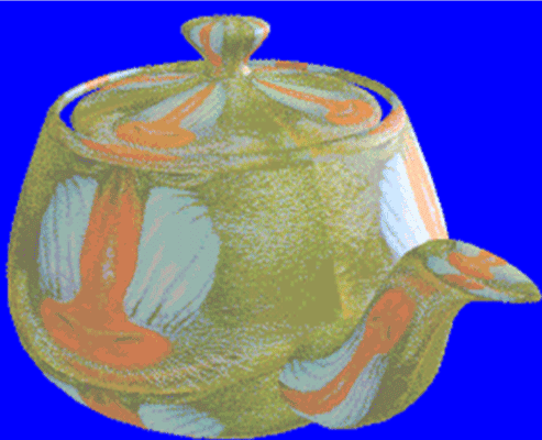
Fig. VI.3. a) Example of Bezier surface, b) Object surface defined by Bezier patches
Zaletą powierzchni Béziera jest to, że manipulując położeniami punktów sterujących można łatwo modyfikować kształt powierzchni. Często model powierzchni składa się z kilku części (tzw. płatów Béziera).
Voxel models
The idea of voxel modelling is to place the modelled object inside the cube. Then the cube is divided in turn to smaller subcubes until the level of the smallest required subcube - voxel. Then we test which voxel belongs to the modelled object. Set of these voxels is desired model of object.
Voxel method is very demanding regarding the memory capacity required to store information about object. Let us assume, for example, that we limit the precision of the model to the cube with the side of 512 units. It means that we must take into account the need to reserve memory locations to store information about 5123 voxels (although the resolution is not very big with respect to needs).
In turn the advantage of this method is that we may associate additional information in the form of suitable attributes with each voxel. In this way we get the model that gives the information not only which voxels belong to 3D object but also about another features of specific elements from the interior of 3D object. Creating, for example, voxel model of a part of human body we may associate with each voxel the information whether in given place is soft tissue, bone, blood vein etc. Having such model is possible to find different cross-sections of human body and for example learn the human anatomy.
As far as the voxel method carries the information about object interior, the information about the outer surface of the object is no directly available.
Methods supporting modelling
In 3D graphics programs we use different methods that make modelling process easier. We will discuss two such methods: CSG and sweep method.
In CSG (Constructive Solid Geometry)method we assume that there is available a set of basic solids (so called primitives), that may be joined into more complex solids. The boolean operation on sets are used here: adding/joining the solids, finding common parts, finding the difference. The examples of the results of such operations are shown in Fig. VI.4

Fig. VI.4. Examples of operations in CSG method. a) Solid adding, b) solid subtracting, c) common part
The next method is called cross-section shift (sweep). In this method we define cross-section of the solid which is then shifted along the given path. During shifting we find lateral surface of the solid. The path may be straight line or may be curve (for example Bezier curve). During shifting we may change the shape of cross-section. In specific case where the cross-section is revolved about specific axis it is possible to create rotary solids. The example illustrating the method is shown in Fig. VI.5.

Fig.VI.5. Modelling in sweep method
3D graphics programs make available tools that enable modification or deforming previously prepared models. The objects may be for example torsioned, bent, narrowed, stretched etc. Examples of such modifications are shown in Fig. VI.6.

Fig. VI.6. Examples of 3D object modifications
Model attributes
Modelling stage gives the information about shape of the object. For correct rendering it is necessary to define attributes of object. Namely the parameters of the surface of the object must be set: colour, the type of material, parameters relevant to texturing etc. The type of material decide on the reflective properties of the surface (sometimes about emissive properties). It enables modelling of the objects with absorbing surfaces, matt surfaces, glossy, shiny or mirror reflective. In addition the final look of the object will depend on lighting, angle of observation etc. Model attributes usually are associated with vertices of triangle mesh approximating lateral surfaces.
Light sources
The light sources are necessary element of 3D scenes. They enable „observation” of the objects located in scene and also finding the colours of objects' lateral surfaces.
In reality the light sources are physical objects having shape and dimensions as all other objects but additionally they emit light. In computer graphics they are most frequently treated as dimensionless, ideal objects - we distinguish point light sources and directional (far) light sources. The area light sources are sometimes used.
Point light source is placed at specific point in the scene. Such source generates the rays going uniformly in all directions. The rays fall upon the object at different angles of incidence. (see Fig.7a).
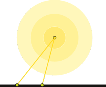
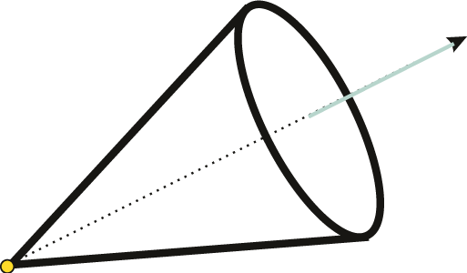
Fig. VI.7. Light sources: a) point, b) conical
The light source may have associated different parameters, such as placement coordinates (x,y,z), colour, intensity, attenuation according to distance d function (for example $f=1/{d^2}\;$). Point light sources are not subjected to rotations and scaling, whereas they may be shifted in the scene.
Sometimes we may limit the spread of rays from point light source, for example to interior of cone with specific vertex angle and main axis direction (see Fig. VI.7b).
Directional lights simulate light sources placed in so large distance, that we may assume that all the rays falling upon the object are parallel (Fig.VI.8). In such situation the direction of rays is relevant while the placement of source has no significance and is not subjected to translation operation.

Fig. VI.8. Directional light
In the case of real area sources all the surface emits light in all directions. In computer graphics the area sources are realised in the way that some number of point light sources is placed on specific surface. The area light sources are used when there is a need to generate soft shadows casted by objects.
Scene modelling
After preparing the models of particular objects and defining their attributes we may proceed to designing the scene which will be then rendered and displayed on the screen. Scene designing relies on transfer prepared component models to single coordinate system (so called world coordinate system) and locating them at proper places. The operations of changing coordinate system and geometric transformation are used.
For full scene definition it necessary to set a background and the way of scene illumination We should choose the light sources, point, directional or conical and place them in the scene. Frequently so called ambient light is defined. It is not associated with any specific light source It is omnipresent and omnidirectional. It enables the visibility of objects even when the object surface is not directly illuminated by existing light sources.
In Fig. VI.9 the example of solid illuminated by different light sources are shown.
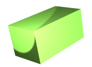
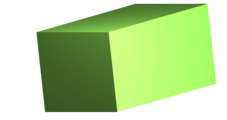
Fig. VI.9. The solid illuminated by different light sources
Defined scene may be observed from different observation points and at different angles. In order to define the way of observation the notion of camera (observer) is introduced. Camera's parameters define its placement, orientation and direction of view. This parameters enable to define the placement of virtual screen where two dimensional view of 3D scene will be projected.
Shadows casted by objects
In real world at specific illumination, the objects cast shadows, so the 3D graphics must take this phenomenon into account. Dependent on the kind of illumination the object may cast deep shadow (umbra) or deep shadow and penumbra.
If the object is illuminated by point light source that the area of deep shadow is generated on the background (Fig.VI.10). In order to define the area of shadow on the background we must find crossing points of rays from light source tangent to the object with the background. Then the area of the shadow should be rendered and appropriate colour should be assigned.

Fig. VI.10. Deep shadow area
In order to get areas of deep shadow and penumbra it is necessary to use area light source (Fig. VI.11). If the area light source is modelled as a set of point sources placed on a plane the each of point light source is considered independently. Deep shadow area is the area where no ray falls upon. Penumbra is the area where some number of rays reach the surface. The intensity level of particular points in penumbra area will be defined by the number of rays reaching this point.

Fig. VI.11. Deep shadow and penumbra areas
In calculations of shadows in scene some accelerating speed of calculation methods are use. One of them uses shadow solid. For defined point light source and certain object we may find this part of space such as that no ray from light source reaches this part. This part of space is called shadow solid. In Fig. VI.12 the shadow solid for combination: point light source and a triangle is shown. Knowledge of shadow solid enables fast testing whether the object or its part lies in shadow or not.

Fig. VI.12. Shadow solid
Another concept is used in the shadow map method. In preprocessing stage, preceding the calculations concerning observation of scene from different camera locations, we perform calculations that will make easier assessment whether the specific point lies in shadow or not.
For this purpose the auxiliary screen called shadow map is placed between point light source and the scene. For each pixel of this map the ray toward the scene is traced and after finding the first object crossed we specify the distance to this object. This distance is written as an attribute of shadow map pixel.
After placing the camera which will observe scene the ray from camera through screen pixel is traced toward scene. After finding the first object hit, the distance between crosspoint P, (between ray and object) and a light source is calculated. If this distance is equal to the value stored in shadow map the point P does not lie in shadow. In opposite case it lies in shadow.
Geometric transformations of 3D objects
Prepared solid models may be subjected to different geometric transformations: translations, rotations, scaling etc. The concept of homogeneous coordinates similar as in 2D graphics is used. With the provision that now each point is represented by four coordinates (x,y,z,1). Matrices for basic transformations are shown below.
Translation about vector ($t_x$, $t_y$, $t_z$)

Scaling with scaling coefficients $S_x$, $S_y$, $S_z$

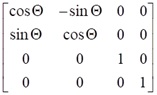
In the case of rotation there are three matrices for rotation about x axis, about y axis and about z axis. In right handed coordinate system positive angle of an object revolution means counter-clockwise direction if we look along the axis towards the origin of coordinate system.
Rotation about x axis

Rotation about y axis

Rotation about z axis
It is possible to concatenate the transformation and finding single resultant matrix for a specified sequence of operations. In particular it is possible to find a matrix for revolution about any arbitrary axis different from the axes of coordinate system.
More complex objects may be modelled using hierarchy concept. Components are joined into one common structure. Then application of transformation of one objects transfers to the associated objects.
Coordinate systems
In modelling stage particular objects may be created in their own coordinate systems. During creation more complex object it is necessary to move components to one common coordinate system. For example when we model a car its body, chassis and wheels may be modelled in independent coordinate systems. During assembling the car parts particular components must be joined in single common coordinate system. Then the full car model should be transferred to scene coordinate system. The highest level of coordinate systems is called world coordinate system.
Change of coordinate system relies on a sequence of geometric transformations: translations, rotations and scaling, which is illustrated in Fig. VI.13. In coordinate system A(x,y,z) another coordinate system B(x’,y’,z’) is placed. The origin of B system is placed at a point, (x0,y0,z0) and the axes are directed according to versors ux',uy',uz'. Transformation between B coordinate system to A coordinate system requires translation of the origin of the B coordinate system about vector T(-x0,-y0,-z0) and then making rotation to align the axes of both coordinate systems. This rotation uses the matrix R, with the elements, who are the component vectors of versors of the axes of B coordinate system. Possibly scaling of the axes of B coordinate system may be required in order to agree dimensioning of axes in both systems.
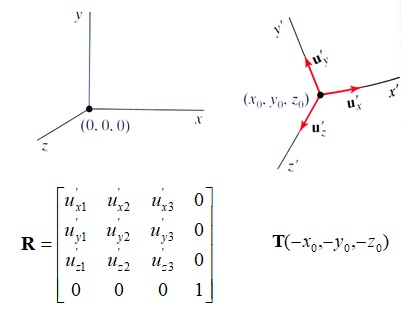
Fig. VI.13. Change of coordinate system
The lecture teach us different problems and methods of modelling the objects and illuminated 3D scenes.
Questions and problems to solve.
- Tell the basic differences between modelling methods: Brep and voxel.
- Sketch a cone and example of approximation of its lateral surface with triangle mesh.
- Find resultant matrix for the revolution about the axis parallel to x axis.
- Explain the difference between point light source, directional and area sources.
- Sketch the scene with a sphere, a cube and a point light source placed over opaque plane. Take into account shadows casted on a plane.