Computer Graphics (GRK)
Lecture VIII
Shading and texturing
In previous lecture we did not deal with problems concerning shading of the objects present in illuminated scene because there are the same, no matter which version of rendering is used. This lecture is devoted to discussion of different problem concerning shading and texturing.
Independent on approved conception of rendering there exists always the problem of shading of lateral surfaces of objects present in scene which requires defining the colours of image pixels. Mane different solution are used in computer graphics. They are adjusted to different requirements facing generated images concerning mainly scene complexity and quality expectations.
In practice we frequently use texturing, which enables direct definition of the look of lateral surface of the object. It may also modify the result of previous surface shading.
Shading
Flat shading
The simplest case is limited to flat shading where each polygon approximating lateral surface of the object is covered with uniform colour. Let us explain this shading method on the example of a cube having blue as its original colour and illuminated by light source with intensity $I_p$. In such case the lightness of certain side walls of the cube depends on the incident angle of rays from light source falling upon this wall.
The lightness/intensity of side wall is defined in the manner illustrated in Fig. VIII.1 - wall intensity is equal to the product of light source intensity and cosine of an angle between normal vector N to the wall surface and vector L pointed toward light source.

Fig. VIII.1. Lightness of the wall dependency on angle of incidence of rays from directional light source
The process of shading the cube should starts from finding the side walls which are directly illuminated by the rays coming from light source. For these walls it is possible to define the angle of incidence of rays upon certain walls and finally the shade of blue colour.
The question arises what colour should be assigned to remaining walls that do not receive any rays from light source. Assigning black colour is counter intuitive. The problem is solved by introduction of ambient light, existing in the whole scene but not associated with any light source. Taking into account ambient light we may assign dark blue colour to considered side walls. The ambient light may be also included in definition of lightness of the walls visible from light source, thus directly illuminated.
After deciding the method of shading we may find the placement of the observer in scene, find the walls visible from this point and display shaded cube. In Fig. VIII.2 two views of a cube from two observer placements are shown. Each side wall has uniform shade of colour - hence the term flat shading.

Fig. VIII.2. The cube illuminated by directional light source. a) view with three directly illuminated side walls, with different angles of incidence for 1,2 and 3 wall, b) view for the observer located at the opposite side of the cube than the light source with three walls that are not directly illuminated by light source. The colour of 4,5 and 6 walls is defined by accepted ambient light
Smooth shading
Flat shading methods works well for simple objects with lateral surfaces containing small number of polygons. In the case of curved side surfaces approximated by polygons (triangles) flat shading results in poor effect. If each polygon is covered by uniform colour, the polygonal structure of approximating mesh may become visible (see Fig. VIII.3). The effect may be removed using smooth shading based on Gouraud method discussed in lecture IV.
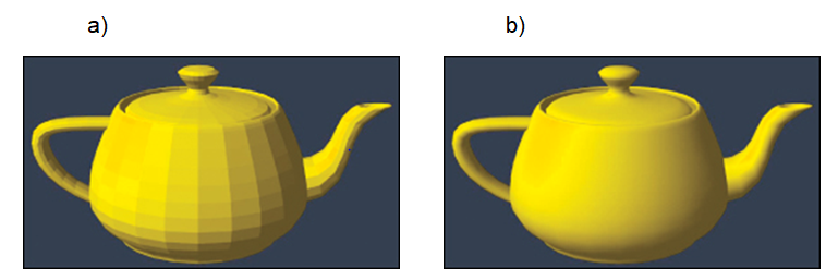
Fig. VIII.3. Examples of sphere surface shading. a) Flat shading method, b) smooth shading method
Let us assume that the lateral surface of the solid is approximated by triangles and concentrate on a single triangle. Moreover we assume that we know the projection of this triangle onto screen surface and the colours (intensity values) of three triangle vertices. These were defined in 3D space before projection. The method of defining the colours of points of 3D space is discussed further. In such case we may use Gouraud method to find the colours of pixels inside the triangle.
Let us notice that during shading two triangles with common edge we will get continuous shading transition between these triangles.
Phong equation
Necessary condition for using smooth shading is knowledge of colours of vertices of certain triangle. It may be treated as special case of finding the colour of point on solid lateral side in scene space.
The basic procedure was proposed by Phong, thus the proposed equation is known as Phong equation. It was derived with the following assumptions:
- The point light source is available
- The light falls upon an analysed point on the surface from one direction and then reflects
- Diffuse reflection and specular reflection (toward the observer) are taken into account
- The ambient light is also taken into account.
General feature of diffuse reflection is that the light reflects from the surface of object uniformly in each directions. The intensity of reflected light depends on the incident angle between incoming ray and normal vector to surface in considered point. With accepted assumptions we may use cosinusoidal dependency (as for flat shading, see Fig. VIII.4a) for calculation the intensity of reflected light.
In the classic mirror reflection the angle of reflection between reflected ray and normal to the surface is equal to the angle of incidence. Phong took into account that some surfaces might not be perfectly specular - in reality there are also glossy surfaces. Phong allows the deviation of real observation angle of considered reflective point from theoretical direction of reflected ray (see angle β in Fig.4b). In the calculations the n-th power of cosine function is used. The value of n is experimentally chosen taking into account the properties of reflective material.

Fig. VIII.4.Illustration of calculations of intensity of point in 3D space. a) Illumination by point light source, b) specular reflection effect
Let us notice that for calculation concerning both diffuse and specular reflections we need to know the normal vector N to the surface at analysed point. If analysed point is a vertex of triangular mesh approximating lateral surface, than the normal vector at the vertex is calculated as an average of normal vectors of all neighbouring triangles transferred to common vertex. Moreover we must know the vector L directed from considered point to the light source.
The basic Phong equation takes a form:
$$I=k_aI_a+k_dI_d\cosα+k_sI_s\cos^nβ$$
In the equation three terms influencing the intensity of surface point are taken into account: ($I_a$), diffusion reflected light ($I_d$) and specular reflected light ($I_s$).
In this equation the coefficients $k_a$, $k_d$ and $k_s$ are weighting coefficient with the values in the range from 0 to 1. They serves for modelling the reflective properties of the surface material.
When there are more light sources in the scene their influence is summed (we should pay attention to not exceed the allowed intensity value. In the case of coloured lights we may used Phong equation independently for each primary colour R,G and B.
Advanced shading methods
In described shading methods we consider only the rays that arrives to shaded surface directly from certain light sources. We skip the fact that in reality the light may come from multiple reflections from other objects. In computer graphic there exist a notion of global illumination which operates on this fact.
Full and accurate calculations of global illumination in practice cannot be realised. Thus some approximated methods were developed. One of this method is previously discussed ray tracing method where during defining the colour of certain point on the surface we take into account the influence of illumination that comes from the objects located on paths in ray spreading tree. Let us note that the global illumination concept eliminates the need of ambient light.
The second element relevant to advanced shading methods is widely understood notion of interaction light - material. In essence it is about more accurate modelling the way that real light reflects from different material, which from the objects may be done.
As it concerns light reflection properties of the surfaces of the objects they may be of different types. They may be smooth, uneven, matt, mirror-like, glossy, semitransparent, absorbing, emissive. For example the light reflects in one way from smooth surface and in another way from uneven surface ( see the Fig. VIII.5) - here the directions of normal vectors in particular points of the surface are shown.

Fig. VIII.5. Example reflection directions from uneven surface
In comparison with Phong simplified model of diffuse reflection in real world the lights arrive at the surface from all possible directions ωi and is diffused into different directions, not necessary in uniform way.
The way of light reflection from the surface made from certain material is described by BRDF function (Bidirectional Reflectance Distribution Function). The function defines what part of light incoming from ωi directions is reflected in each output directions ωo.
The BRDF functions may be defined theoretically on the base of physics, or experimentally during measurements. In computer graphics the most frequently we used simplified functions elaborated by many scientists for simulation light reflection effects for different materials. The functions (models) of Blinn-Phong, Cook-Torrance, Ward, Oren-Nayar may be mentioned.
This functions are used for light reflections directly from the surface of the object. In computer graphics we consider the situations where the light not only reflects from surface but it penetrate under the surface, and after a few internal reflections is emitted outside. It is described by BSRDF (BSSRDF - Bidirectional Sub Surface Reflectance Distribution Functions). For example they are used to model human skin.

Fig. VIII.6. Illustration of subsurface reflection
Texturing
We frequently want to cover outer surfaces of objects by some patterns. For such purposes we use the concept of surface texturing. The concept assumes that we have prepared in advance appropriate pattern - the texture and then such pattern is transferred onto object surface. In Fig. VIII.7 some examples of texture patterns and textured object are shown.
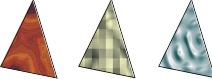
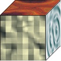
Fig. VIII.7. Examples of texturing
The texture may be any arbitrary bitmap. In particular it may be an image obtained from the scanner or digital camera. Texture is usually defined in coordinate system u,v or s,t. The elementary fragment of texture is called texel.
In the simplest case when the texture area is compatible with flat surface area on which the texture should be applied, the task is simple and is reduced to mapping particular texel to image pixels in x,y coordinate system as shown in Fig. VIII.8. In general we have to find correct method of mapping.

Fig. VIII.8. Basic concept of texturing. In the simplest case one texel is mapped onto one pixel
Above we used grid eyelets model. Then we will use grid nodes model.
In practice different methods of texture mapping are used. In the case of simple models we may use analytical mapping. For example if we have to map texture onto lateral side of cylinder we may use the function that describe point P location on the surface of cylinder in the form
$$\bi p(θ,y)=⟨r\sinθ,y,r\cosθ⟩$$
where θ,y coordinates mean respectively: angle θ measured with respect to zero angle associated with chosen vertical axis on the surface of the cylinder marked by black line, and y is height defined with respect to the point lying at the half of the height of cylinder h. For such defined point P on the surface of cylinder, the coordinates of texel that will be mapped onto point P may be found from equation

Texturing process is illustrated in Fig. VIII.9.

Fig. VIII.9. Example of analytical texturing
In similar way we may solve the process of sphere texturing. But if the surface of the solid cannot be described in such way that there is easy to find equations for mapping the texture onto point of the surface, we may use indirect method. At first we surround the object by auxiliary solid easy to be mapped with texture. It may be a sphere, cylinder or a cube. In next stage the texture from auxiliary solid surface is mapped onto the target solid. The mapping may be done in different manner. The example of solution is shown in Fig. VIII.10.
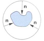
Fig. VIII.10. Illustration of indirect method of texture mapping
In practice we frequently use so called UV mapping. In such case during definition of triangle mesh approximating the object surface the texture coordinates u,v are assigned to each vertex of triangle from the mesh. During texturing on the base of these coordinates appropriate triangle is restored in texture area (see Fig. VIII.11). Then for each next pixel of textured triangle barycentric coordinates α,β,γ are defined (obviously we know the coordinates x,y,z for each triangle vertex). Knowing these barycentric coordinates we may find specific value of texture in a triangle in texture area.

Fig. VIII.11. Illustration of UV texturing method
The assignment of coordinates u,v to vertices of triangle mesh may be done directly by the designer. It is possible to use auxiliary programs that allows spreading the triangle mesh onto a plane, superimposed it onto texture pattern and automatic assignment of coordinates u,v to respective vertices of mesh.
During finding the value of a texture for certain pixel it may happen that calculated texture coordinates will indicate the point lying in the eyelet of texel mesh (Fig. VIII.12). Then we may take the texel closest to considered point or by the use of linear interpolation find the resultant value from four neighbouring texel. The problem is called texture filtration.

Fig. VIII.12. Illustration of texture filtration problem
Up to now we tacitly accepted that applied texture substitutes earlier colours of particular points of the surface. But it is possibly to use the texture for modifying earlier colour of the surface. We may use product or summing the colours of the texture and the surface. We may perform operation of mixing (blending) two colours $c_1$ and $c_2$ with appropriate ratio defined by parameter $α (α∈(0,1))$.
$$c=αc_1+(1-α)c_2$$
Textures may bear not only the information about colours. The may contain another information. For example it may be height. In such case each texel defines the height that the point should be raised to along the normal to the surface.
In this lecture we learned different shading and texturing methods. The choose of the method depends on particular application area.
Questions and problem to solve.
- Compare the method of flat shading, smooth shading and using the Phong equation.
- What operations are necessary to obtain an image of green cube illuminated by directional light source on the screen. Observer may be located at any point outside the cube.
- The cube and the cylinder are placed over opaque surface. Over these solids the point light source is placed. Sketch the scene taking into account shading of the surfaces of solids and the shadows casted.
- Tell the difference between surface shading and texturing.
- Explain triangle texturing method if we know the coordinates (u,v) for each vertex.